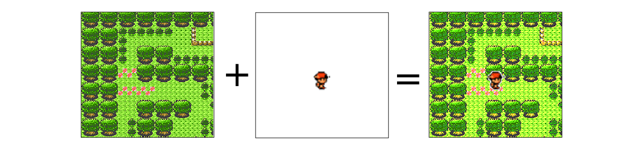
Hello Everyone! Today I’ll be writing about how we can combine game sprites together using basic logical operations like AND, OR and NOT. For this simple example I’ll be using video game sprites from one of my all-time favorite games, Pokémon silver. Before that, below are some basics on logical operations that I’ll be using,
Some Basics(Skip to pokemon example)
First of all a brief introduction to images. I’m sure you all know something about different types of screen resolutions like HD, 488p and so on. The difference between these types of resolutions are the number of pixels in a given view. Think of an image as a 2D grid of small squares where each square represents a dot of color, and higher the resolution the larger the number of squares in a picture. These squares are called pixels. In a digital image a pixel stores some kind of numeric value, where each numeric value represents some color. For example in grayscale images the value 0 represents black and 255 white and all integers between are shades of gray.
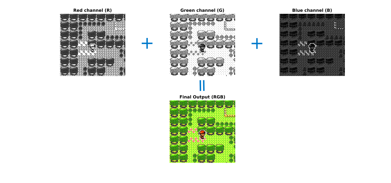
We all know that the three primary colors are red, blue and green. Likewise, color images (RGB) are represented as a combination of three channels or sub-images for red, blue and green as shown below. Each of these sub-images are represented in grayscale. In fact these sub-images don’t really have a color per-say, rather some intensity vale[0-255] which is shown in shades of gray.
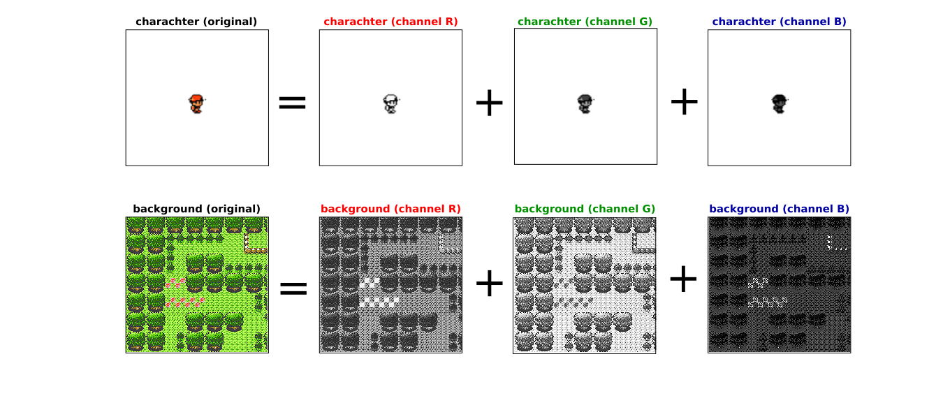
The character image above is mostly red, therefore the red-channel has values closer to 255 which is why that channel looks brighter than opposed to the blue-channel which is very dark. Similarly, for the background, the green-channel is the brightest image because the original background shows a forest.
Logical operations in Image Processing
The basic logical operations in image processing are the same as in arithmetic AND, NOT and OR.

For logical operations to work on images, the images need to be of a specific type called binary. As the name suggests the pixels of these images could only have two values 1 (for white) or 0 (for black).
1) NOT operation
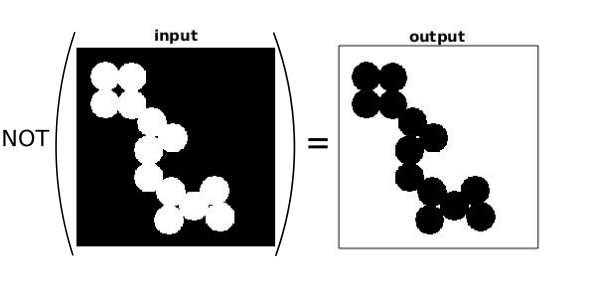
The NOT operation inverts a given input value(0 to 1 & vice-versa), it’s the same principle for images where instead of one single point or location entire regions get inverted depending on their pixel values; so a black area become white or a white area becomes black respectively.
2) OR operation
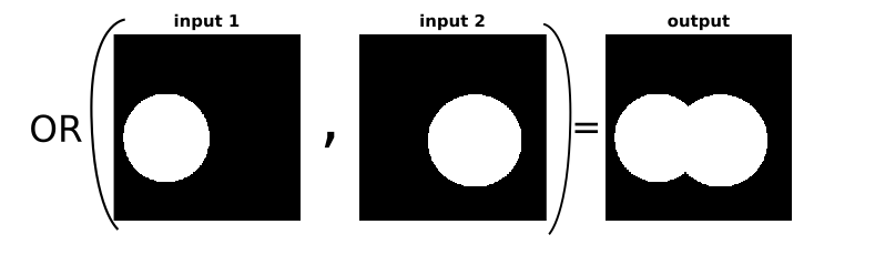
The OR operation combines two binary images such that value 1s of both images show up in the final output. That’s the reason the combination of both the white circles are present in the above output image.
3) AND operation
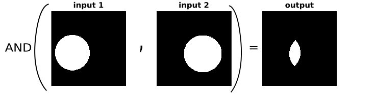
The AND operation functions in a similar fashion as described in the table above. In this example unlike in the OR case, only the intersection of the two circles are shown in the output. Here the output only shows a high value (i.e., 1) when both images represent a high value for the same (x,y) coordinate respectively.
Combining game sprites
From here on, I’ll be explaining the main steps in combining image sprites. I’ve used the software platform Matlab for this demonstration. Also note that in the code examples I’ve used a function, the reason being the steps I explain below need to be operated three times iteratively for all red, blue and green channels of a given image. If you aren't familiar with Matlab image processing toolbox click here and if you need a refresher on Matlab functions click here :). (Click here to go directly to the CODE)
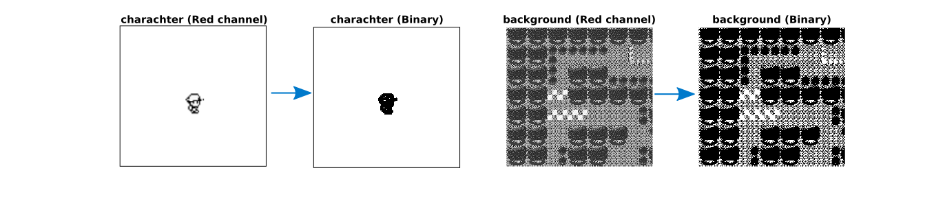
Step 1 : Converting RGB images to Binary images
The first step is to convert our input images to a binary format so that we can use logical operations. Initially we separate the three channels of red, green and blue and afterwards convert them to purely black and white. In matlab we can do this using a function called im2bw(). The images below show the output for this step.
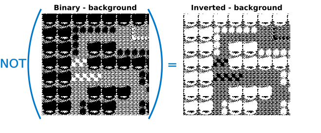
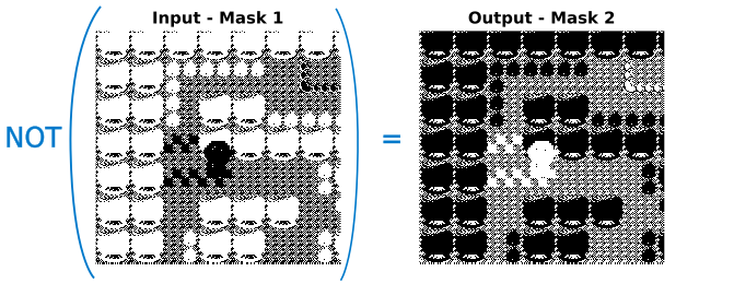
Step 2 : Create an inverted mask of the binary background image
The second step is to create a temporary image or mask which is an inverted output of the binary background image.
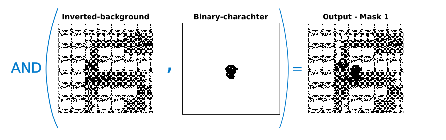
Step 3 : Create the first temporary mask
In this step a temporary mask is created using the two output images from steps 1 & 2. The AND operations is used on the inverted-background image and the binary-character image in order to get a mask with a certain property. If you look closely at the output image, all the pixels describing the character are black (value 0) whereas the rest of the background is the same. Which means any operation done on this mask would only affect the background and the character portion of the image will remain unchanged.
Step 4 : Create the second temporary mask
To get the second temporary mask, the NOT operation is used on the Mask image obtained in the previous step. Here the output image is such that all the background pixels remain in its binary state whereas the character portion becomes value 1 or white. Therefore, any operation done to the image will only affect the character and the background will be unaffected.
Step 5 : Process Masks with original images
By now we have two separate binary masks that are used to manipulate color intensities of the character and the background separately. The pixel intensities for the original images for each channel(red, green or blue) vary between 0 and 255. In order to get this range into the obtained masks, each mask is point-wise multiplied by the respective input images.
So what’s this point-wise multiplication? Earlier I explained that images are like a 2D-grid, and they are stored in matlab as a 2-D matrix. Usually in matrix multiplication, a row is multiplied by a column of another matrix and all the individual values are summed together to obtain a value of one cell in a new matrix. However, in point-wise multiplication each cell indexed some (x,y) of matrix A is multiplied by another cell of index (x,y) of some matrix B to obtain the answer. Here there is no summation or rowise/column-wise multiplication.
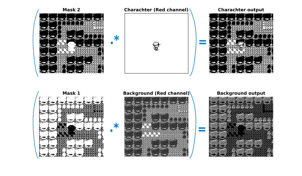
If you look closely at the output images. The character image has the original character in the image in addition to a binary representation of the background. In the background output image, the background pixels have the same intensity values as per the input image whereas the character section is binary. Basically, the only step left to take is combine these two separate output images into one single image.
Step 6 : Combine the character image and background image
This step is all about combining the separate outputs into one. There are a couple of ways to go about this step, in my case I opted to go by selecting the maximum pixel intensity for each (x,y) coordinate of both the output images and creating a new image with this maximum value. My rational for this method was that the intensity distribution for every pixel would be definitely between 0 and 255, thus by selecting the maximum at each point I’d minimize the probability of selecting a stray 0 (black) pixel.
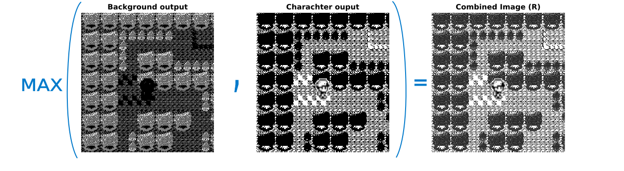
And there you go!!! :) This is the combined image for the red channel from separate sprites for a game character and a specific background.
Step 7 : Combine separate channels (R,G,B) into a color(RGB) image
The final step is all about iterating the above steps from 1-6 for each color channel and combining them together in order to create a color image. This step is crucial for a color image, because the output from step 6 only shows a distribution of intensity values for a given image, The only reason we see the differences in shades of gray is because we map those intensity values to some color scale. Therefore, to combine the separate channels a new image is created of type unit8 and the outputs from step 6 combined into it.
Code
The driver code
clc;
clear;
man = imread('silver.png'); % loading images
back = imread('background.png');

man_r=man(:,:,1); % separate input character image to r,g,b channels
man_g=man(:,:,2);
man_b=man(:,:,3);

back_r = back(:,:,1);% separate input background image to r,g,b channels
back_g = back(:,:,2);
back_b = back(:,:,3);

temp_r = combine_image(man_r,back_r); % process using function()
temp_g = combine_image(man_g,back_g);
temp_b = combine_image(man_b,back_b);

final_image = uint8(zeros(size(man)));
final_image(:,:,1)= temp_r; % step 7 -combine output images to a single color image
final_image(:,:,2)= temp_g;
final_image(:,:,3)= temp_b;

figure;
imshow(final_image);
The Function
function temp = combine_image(man,back)
    man_b= im2bw(man,0.99); %  step 1
    back_b = im2bw(back);
    not_back = not(back_b); % step 2
    com = and(man_b,not_back); % step 3 - Mask 1
    com1 = not(com); % step 4 - Mask 2
    with_man = com1.*double(man); % step 5
    with_tree = com.*double(back);
    sz= size(com);
    for i = 1:sz(1,1) % step 6
        for j=1:sz(1,2)
            temp(i,j)=max(with_man(i,j),with_tree(i,j));
        end
    end
    temp = uint8(temp);
end
I know this post was a bit long, but this is a cool example of some basic image processing techniques. If you want to learn more click here for a reference to a great book.
So until next time.
Cheers !!
Next: Simulation of Hard Disks: Part 1
Prev: Simulation of a serial snake robot